Piping instrumentation exchanger reactor
Table of Contents
Table of Contents
Are you interested in creating piping and instrumentation diagrams for your engineering projects but don’t know where to begin? Don’t worry; drawing piping and instrumentation diagrams might seem like an overwhelming task at first, but it’s not rocket science. It’s a skill that can be learned with practice.
Developing clear and detailed piping and instrumentation diagrams is essential for any engineer or designer. However, it’s not always easy to know where to start or what to include. Designing a piping and instrumentation diagram requires careful consideration of the system’s components and the relationships between them. It also requires a basic understanding of the symbols and conventions used in these diagrams.
To start, it’s important to understand what a piping and instrumentation diagram is. It is a detailed schematic drawing that shows the process flow within a plant or industrial facility. It represents the interconnection of process equipment, control instruments, and piping systems. The diagram is used to communicate the design and functionality of the system to stakeholders involved in the project such as operators, engineers, and contractors.
To create a piping and instrumentation diagram efficiently, you must follow a few essential steps. First, define the scope of the work and the intended audience. Next, gather all relevant data including process specifications, equipment specifications, and control instrumentation. Then, determine the system’s boundaries and develop the schematics. Lastly, verify the accuracy of the diagrams and review them with your team to ensure everyone understands the system design.
My Experience with Drawing Piping and Instrumentation Diagrams
When I was first tasked with creating a piping and instrumentation diagram, I was somewhat intimidated. The symbols and conventions used in these diagrams were new to me, and I wasn’t quite sure where to begin. However, with some guidance from my team, I quickly became proficient in creating these diagrams.
One of the most crucial aspects of creating an effective piping and instrumentation diagram is using the right symbols. These symbols represent the process equipment and control instruments that are being used in the system. The use of the right symbols in a piping and instrumentation diagram is critical to ensure that the diagram is clear and understandable.
The Main Points to Consider When Drawing a Piping and Instrumentation Diagram
When creating a piping and instrumentation diagram, it’s crucial to remember that the diagram should be easy to read and understand. To achieve this, you need to follow established standards and conventions for symbols, labels, and notations. Additionally, proper labeling and numbering of process lines, instruments, and equipment is essential for understanding the system’s design.
Another essential element of piping and instrumentation diagrams is accuracy. The design must match the actual system’s layout and be updated regularly to ensure the information remains accurate. Regular updates are essential since the system can undergo changes over time.
Understanding the Symbols on a Piping and Instrumentation Diagram
Before you begin drawing a piping and instrumentation diagram, you should have a fundamental understanding of the symbols and conventions that are commonly used. Some of the most commonly used symbols include valves, pumps, motors, and control instruments. It’s also essential to know the different types of lines and arrows used in these diagrams and understand their meanings.
Best Practices when Drawing a Piping and Instrumentation Diagram
When creating a piping and instrumentation diagram, there are some best practices to keep in mind. First, it’s essential to have a clear understanding of the system’s design requirements and specifications. Next, you should use a standardized system of labeling and numbering equipment and instruments. Finally, once the diagram is complete, it should be reviewed by a team of experts to ensure accuracy and completeness.
Question and Answer Section about Drawing Piping and Instrumentation Diagrams
Q: How do I determine the system boundaries for a piping and instrumentation diagram?
A: Start by gathering all the relevant information regarding the process, including equipment, control instruments, and piping systems. Determine the beginning and end points of the system and focus on the system’s primary function.
Q: What is the importance of accurate labeling on a piping and instrumentation diagram?
A: Proper labeling ensures that the diagram is clear and easily understandable. It also helps to prevent errors in the installation and maintenance of the system.
Q: How do I ensure that my piping and instrumentation diagram is accurate?
A: Regular updates and reviews by a team of experts are the best way to ensure that your piping and instrumentation diagram is accurate. You should also use a standardized system of labeling and numbering equipment and instruments.
Q: Can I use software to create piping and instrumentation diagrams?
A: Yes, there are many software applications available that can help you create piping and instrumentation diagrams. These programs are easy to use, and they often have built-in libraries of symbols and templates.
Conclusion of How to Draw Piping and Instrumentation Diagrams
To sum up, creating a piping and instrumentation diagram is a vital skill that is essential for any engineer or designer. By following best practices and established standards, you can create clear and accurate diagrams that are easily understandable by all stakeholders. Proper labeling and symbol usage are critical for the success of these diagrams, and regular updates and reviews are crucial to maintain accuracy over time.
Gallery
P&ID Guidelines For Separator Vessels - Inst Tools
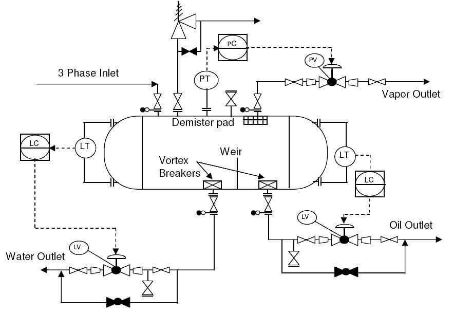
Photo Credit by: bing.com / separator phase diagram piping instrumentation pid typical symbols process arrangement vessels symbol horizontal drawing gas control oil pressure example air
Chemineering: Types Of Chemical Engineering Drawings - BFD, PFD, P&ID
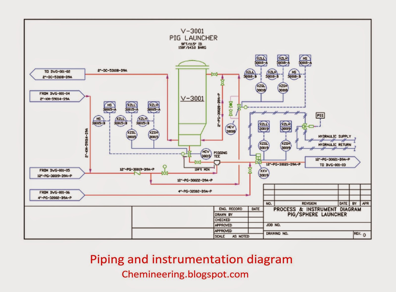
Photo Credit by: bing.com / chemical engineering diagram piping instrumentation pfd drawings types tr control pid bfd layout electrical steam oil system boiler pipes seç
How To Read Piping And Instrumentation Diagram(P&ID) | Piping And

Photo Credit by: bing.com / piping instrumentation exchanger reactor
P&ID Software - Get Free Symbols For Piping And Instrumentation Diagrams
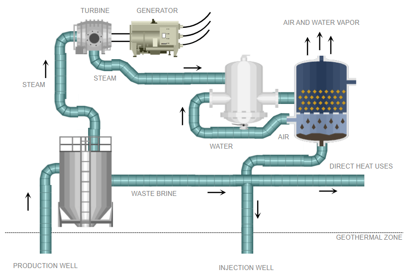
Photo Credit by: bing.com / instrumentation software patent diagrams symbols smartdraw cad
Identify Instruments In Piping And Instrumentation Diagram
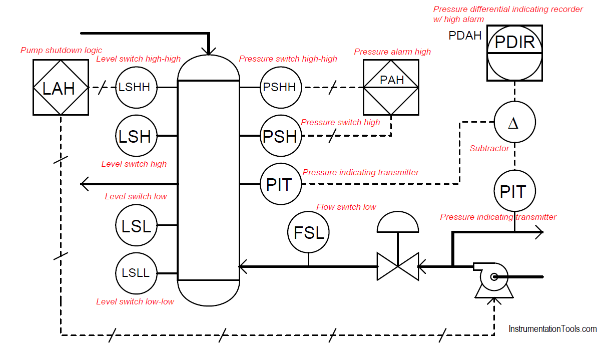
Photo Credit by: bing.com / piping instrumentation abbreviations kuphaldt


